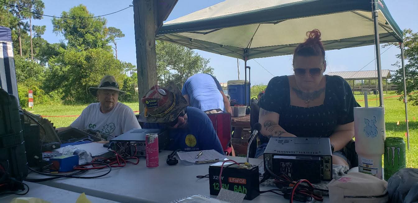
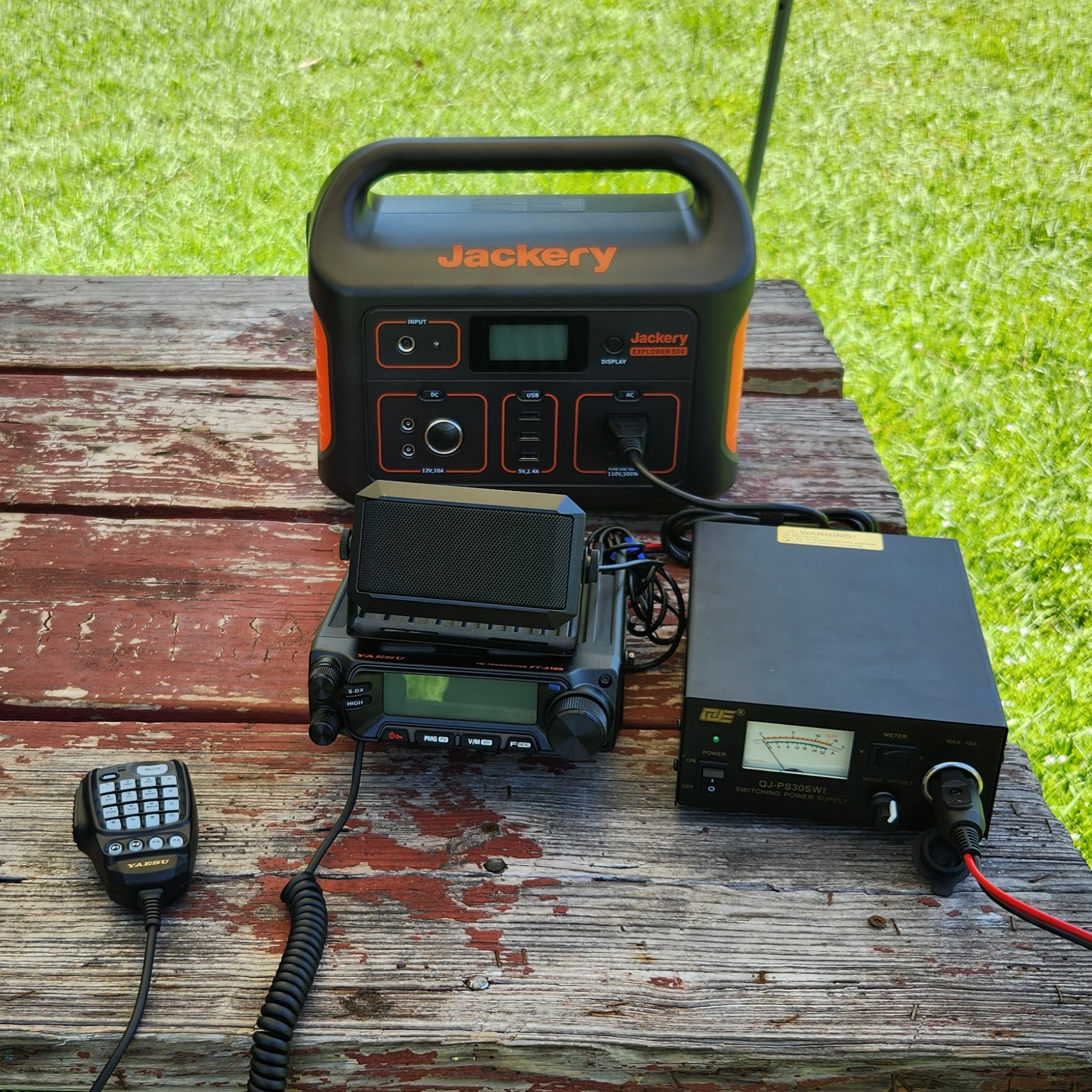
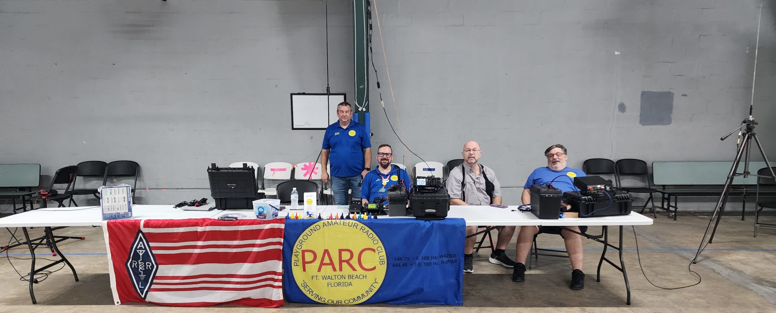
During break at the Playground Amateur Radio Club General Class we took some time out to show off the Digital Station at the Clubhouse!
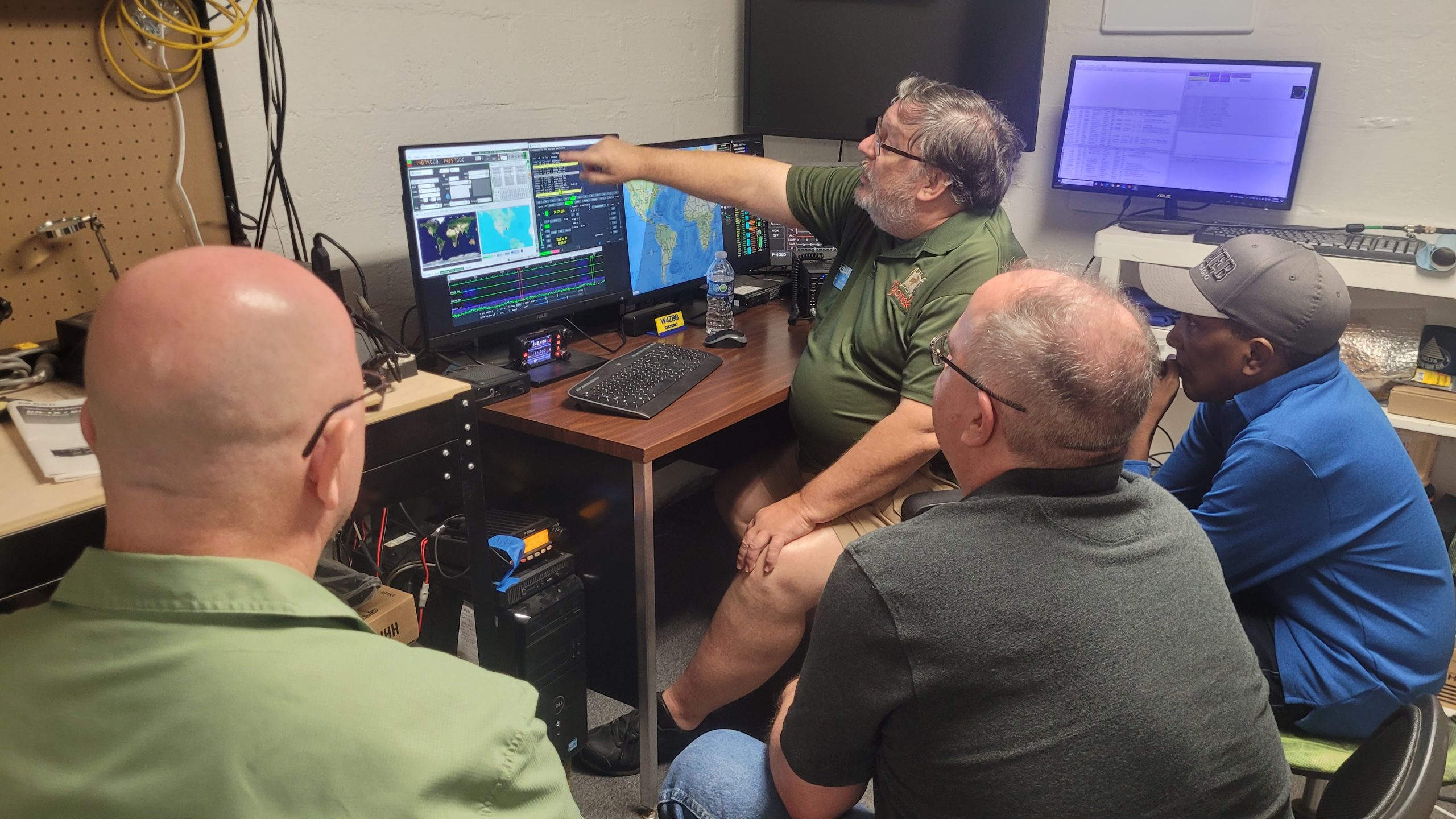

During break at the Playground Amateur Radio Club General Class we took some time out to show off the Digital Station at the Clubhouse!
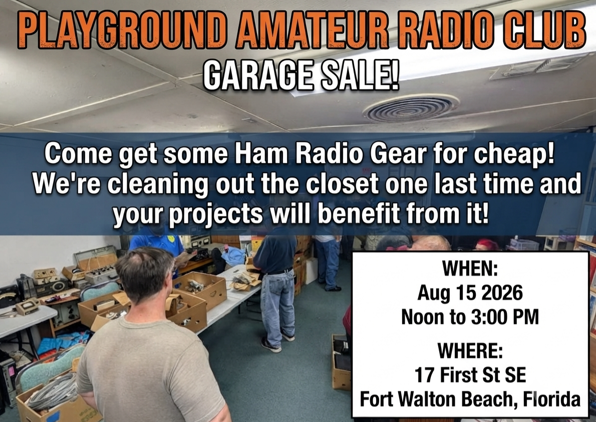
Playground Amateur Radio Club Garage Sale! Come get some Ham Radio Gear for cheap! We’re cleaning out the closet one last time and your projects will benefit from it! Noon to three pm Aug 15 2026!
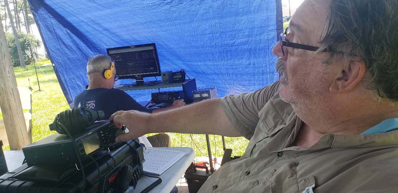
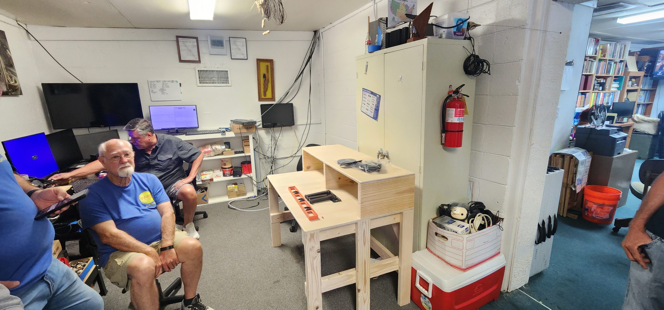
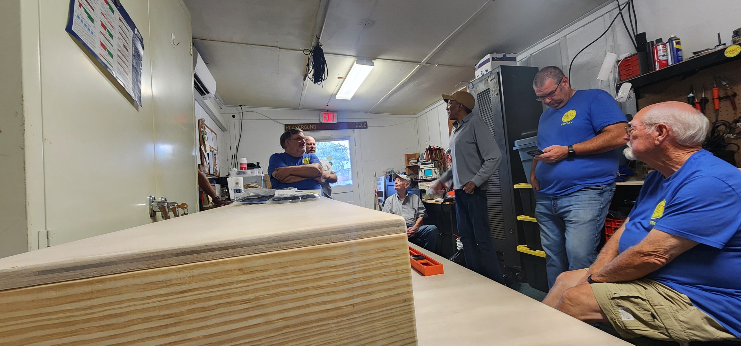
Pardon our progress! The Playground Amateur Radio Club is currently revamping station 1 for the future of PARC communications!
Liza Jackson Park Fort Walton Beach Sat 1200 to 6 and Sunday 9 to 1200!
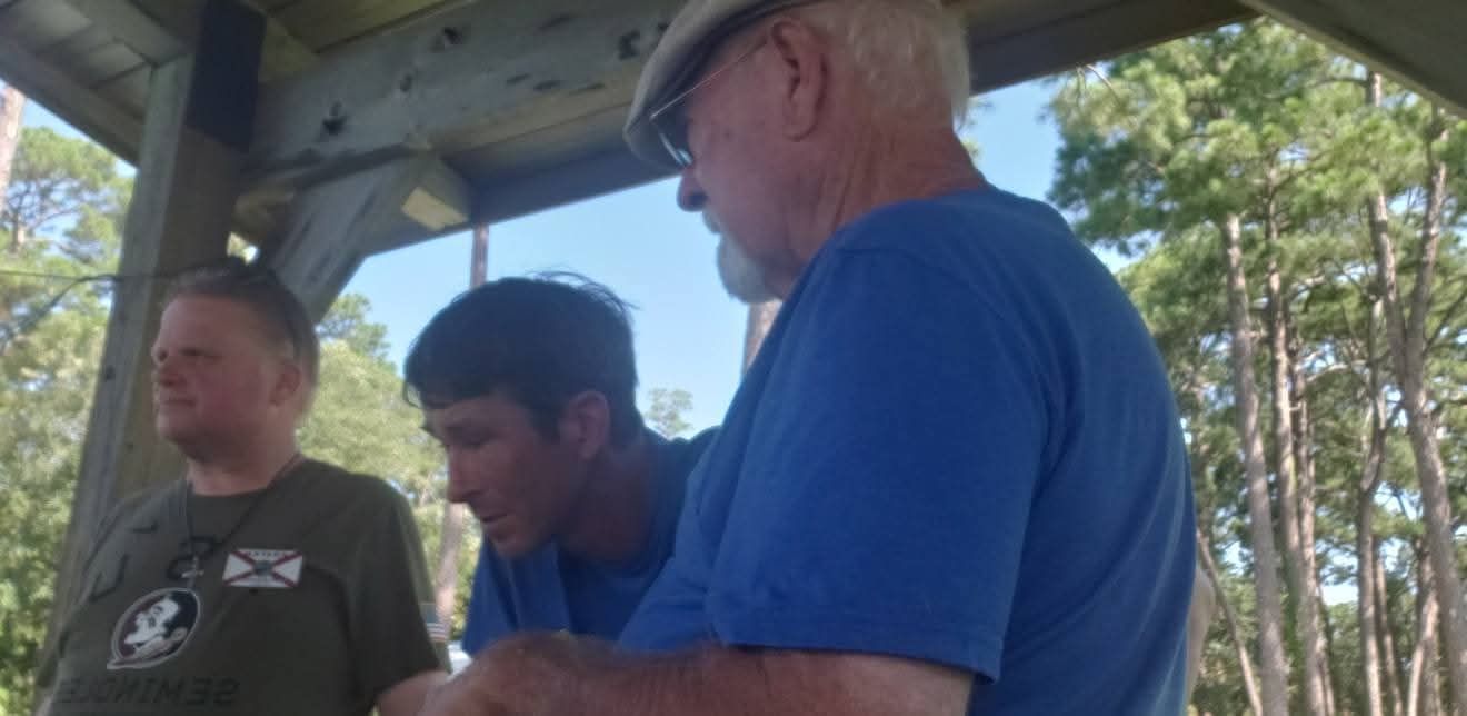
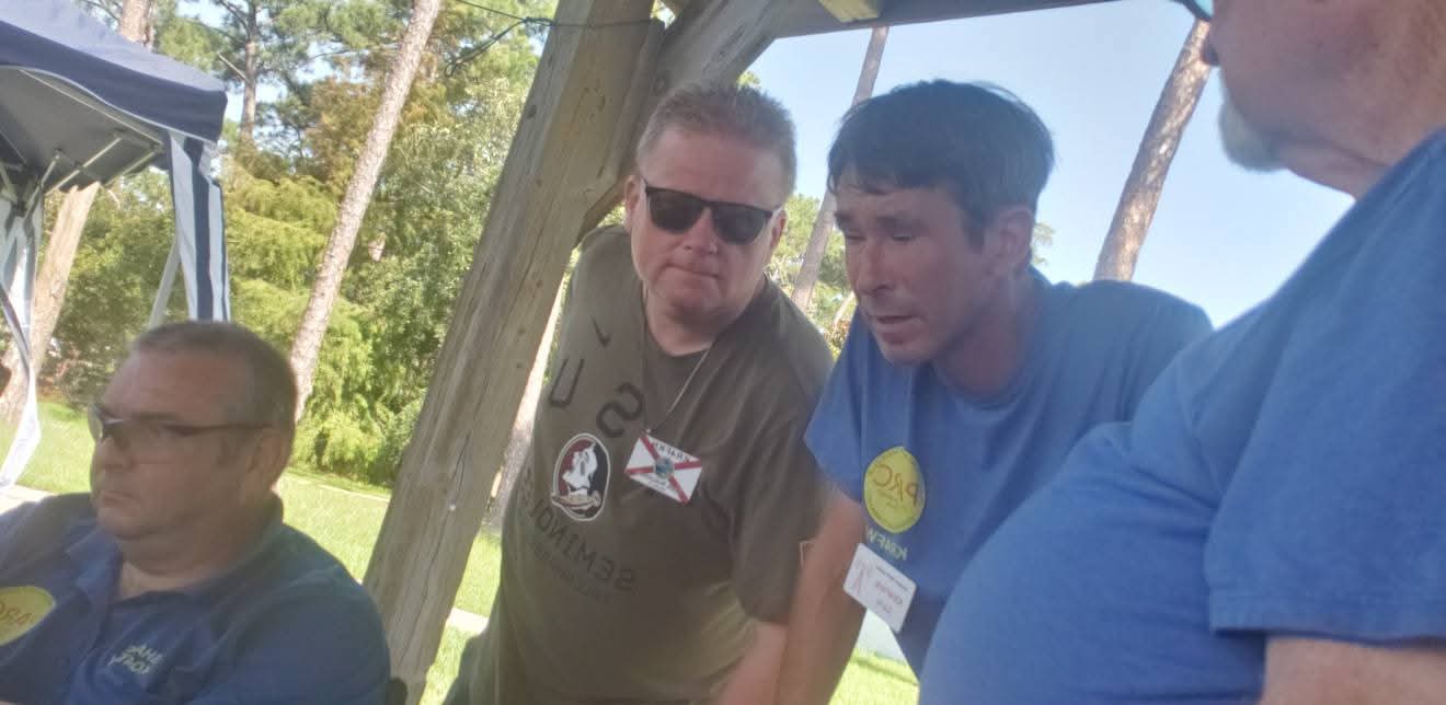
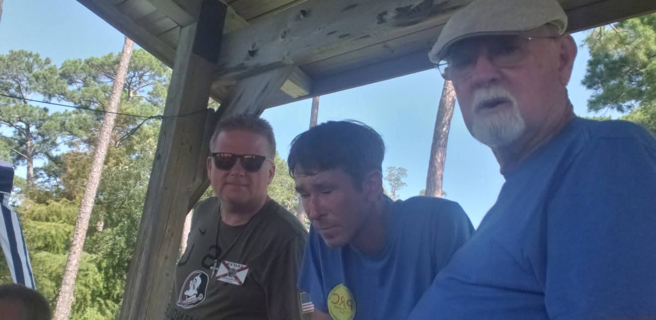
General Class at PARC has the bandwidth! Lessons are being taught and the energy is enthusiastic!
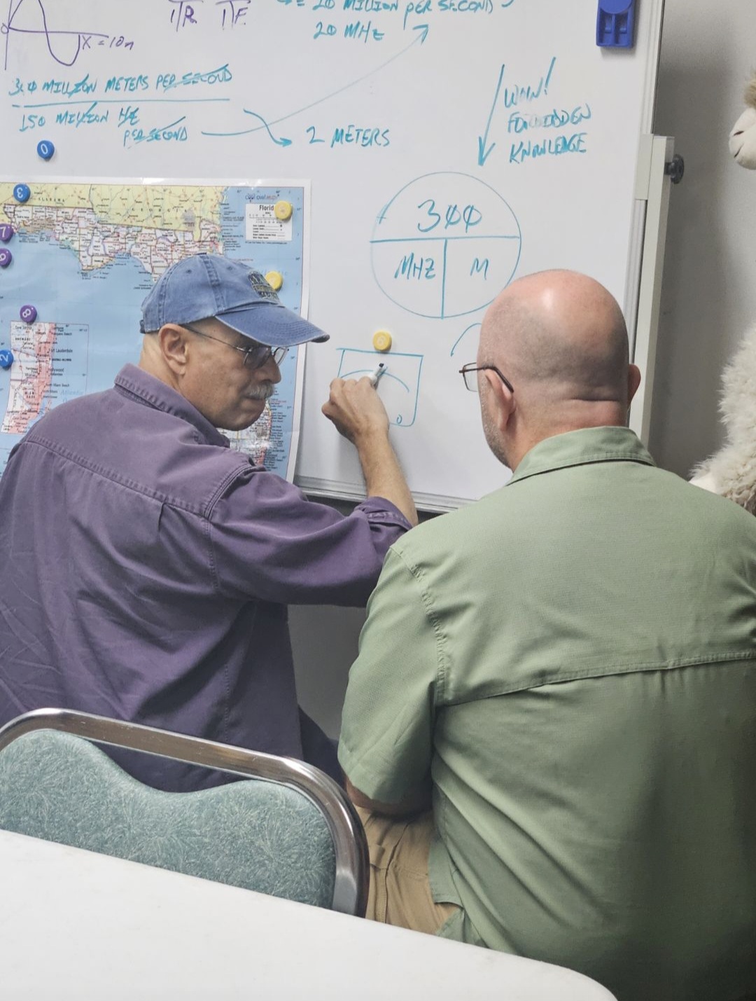
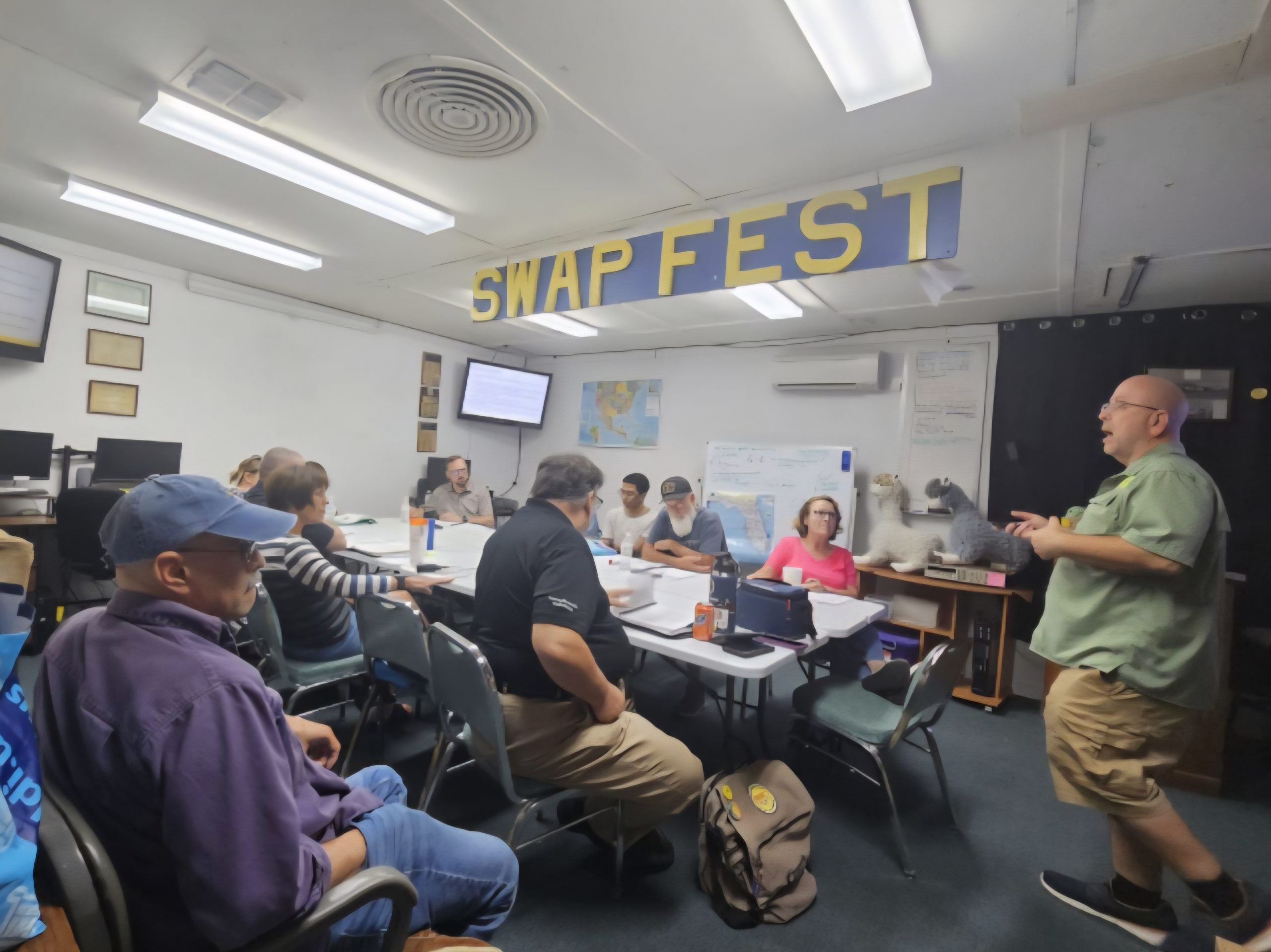
…And Boy Howdy!
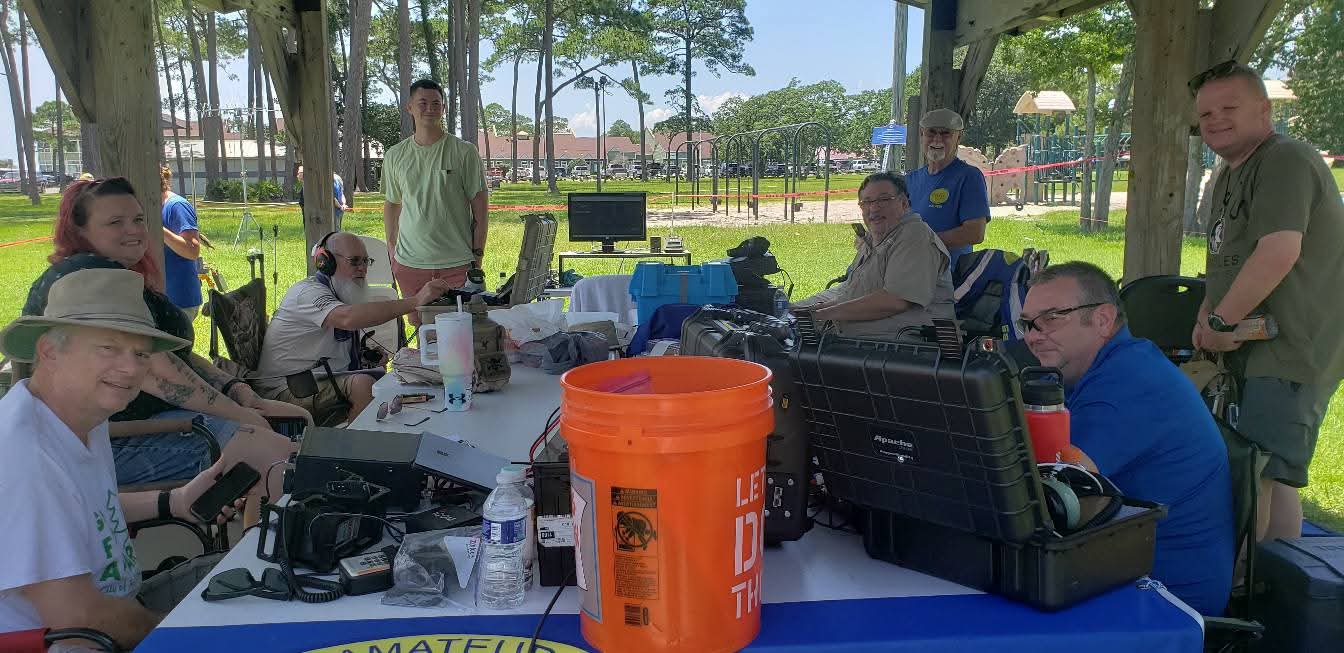
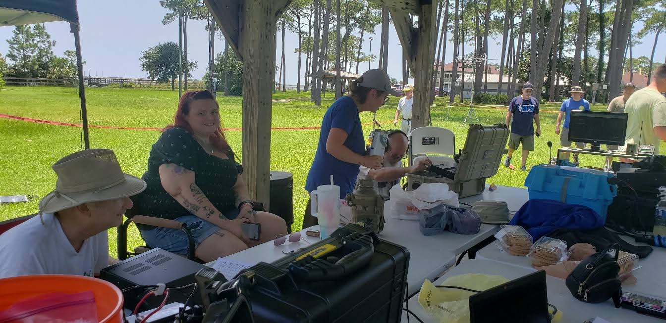
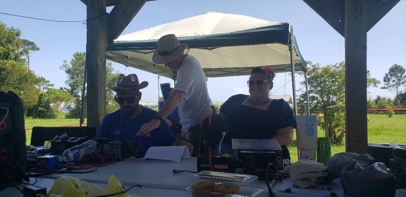
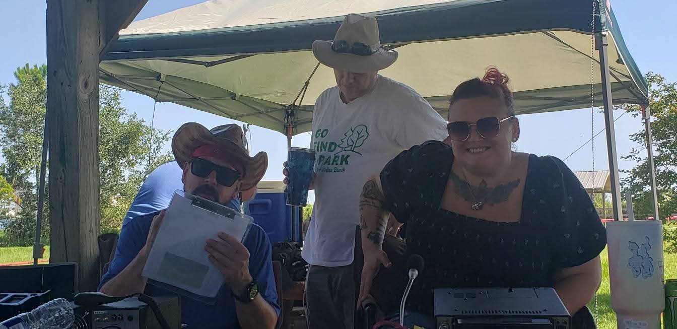
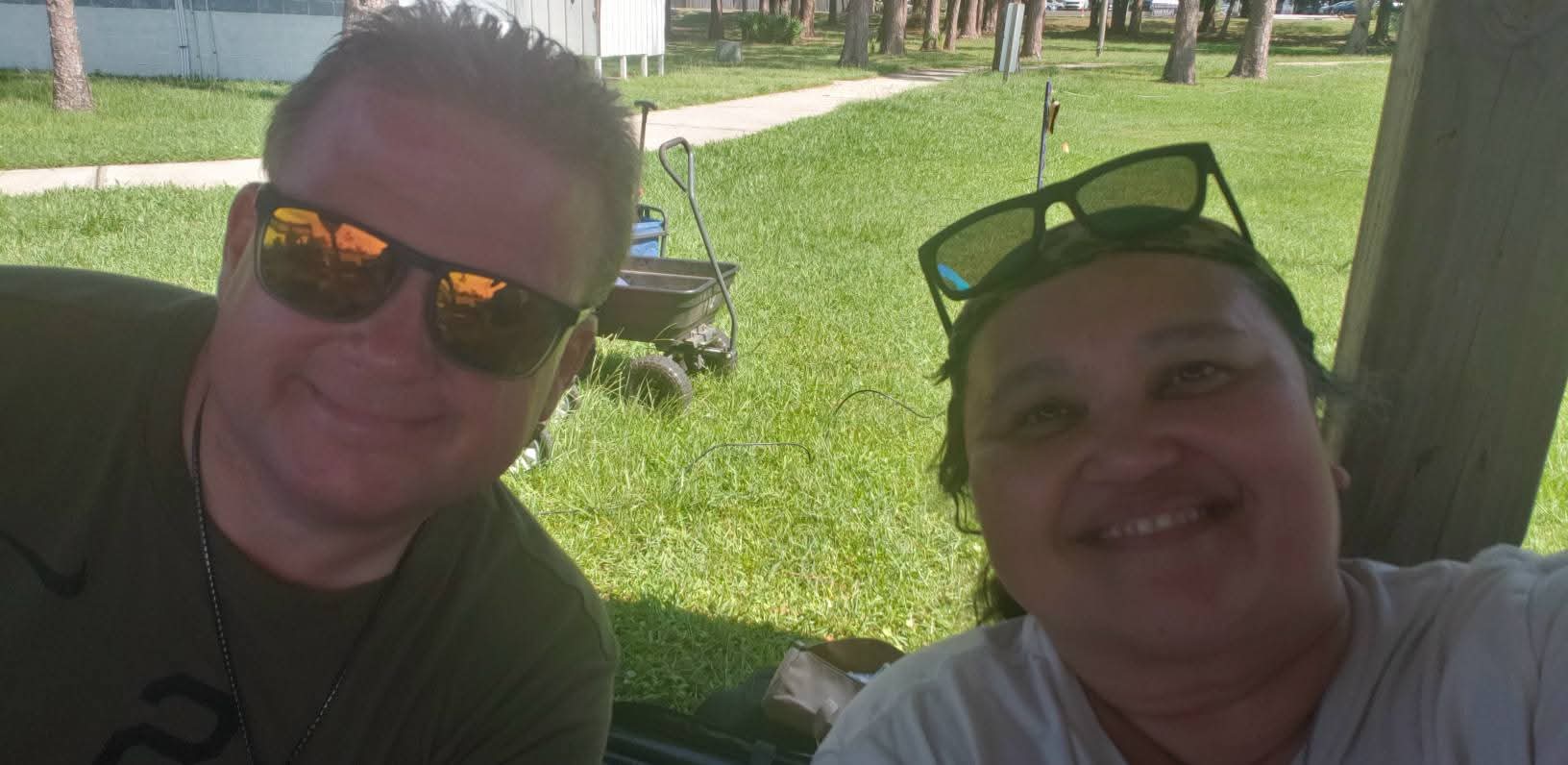
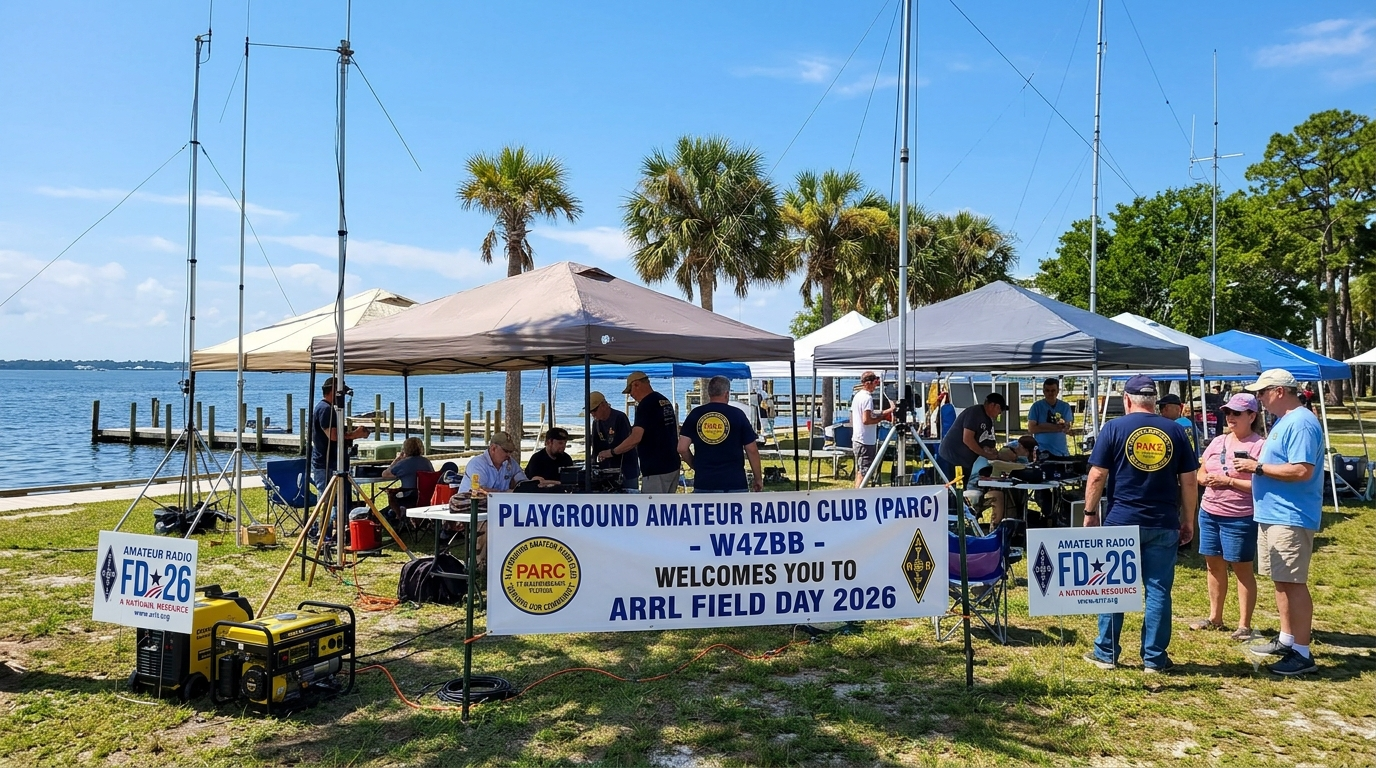
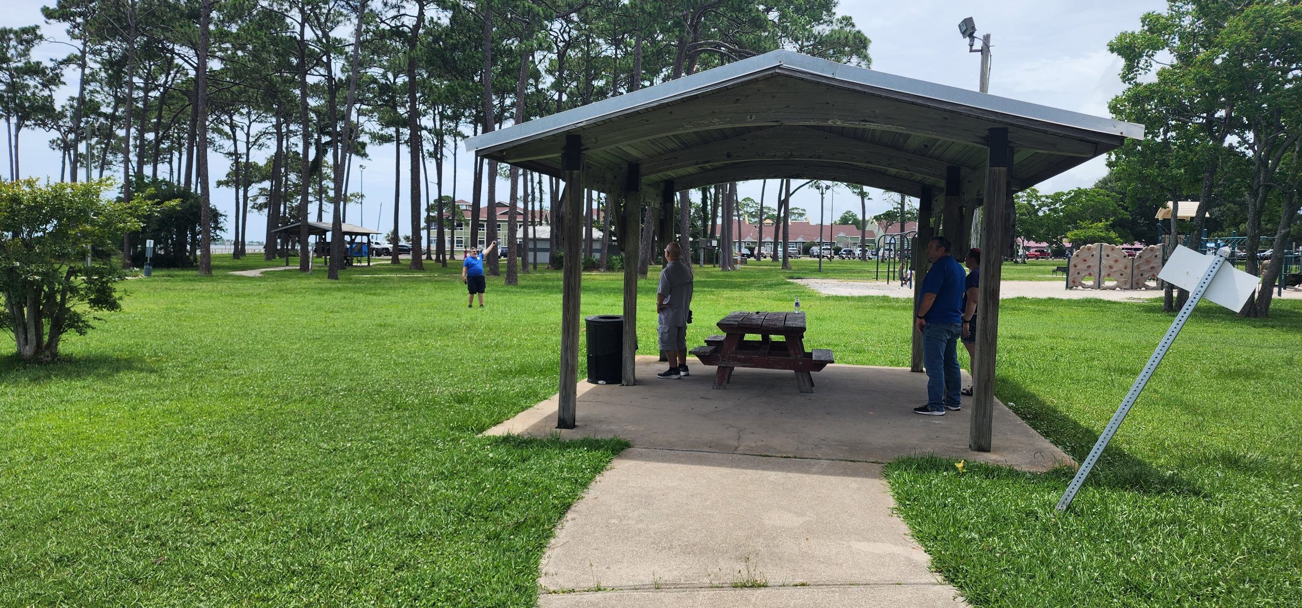
Hope your Sunday is a hamtastic day! PARC started off at the Panhandle United Roller Derby Junior Bombers Market! We demonstrated the ease and use of Amateur Radio while also continuing the public role of representing Amateur Radio!
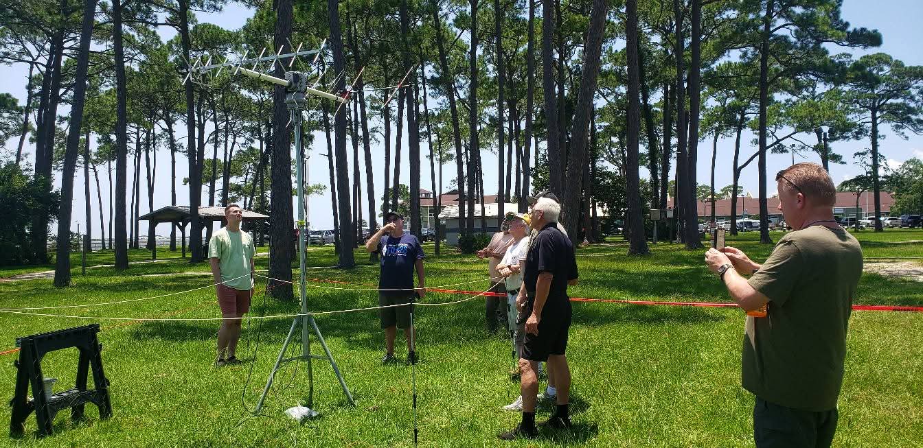
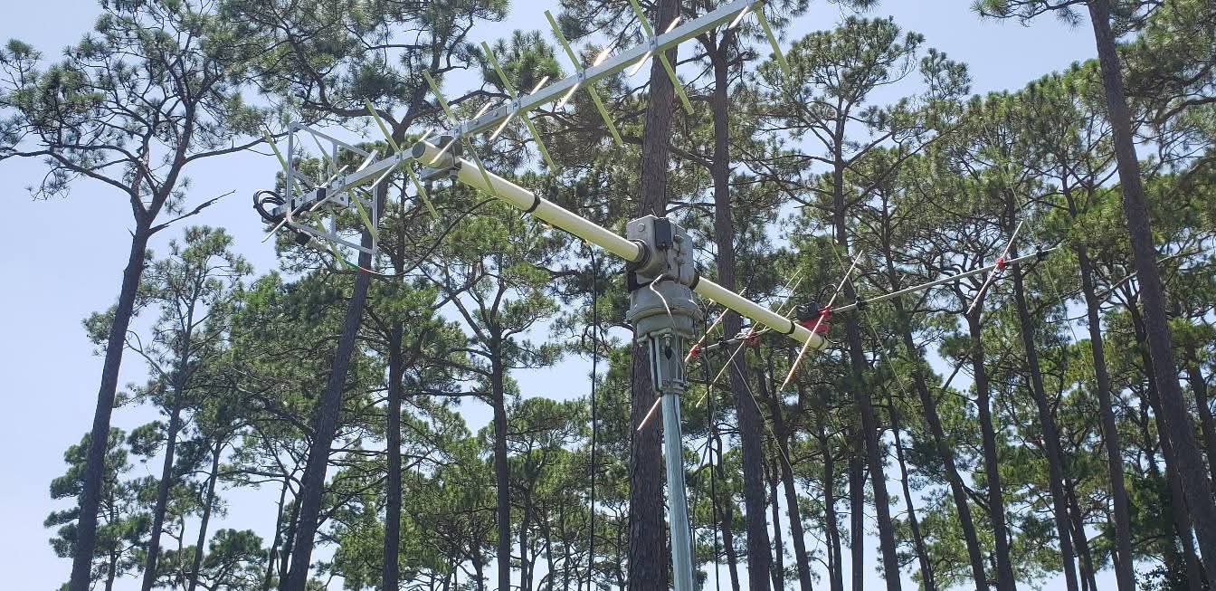
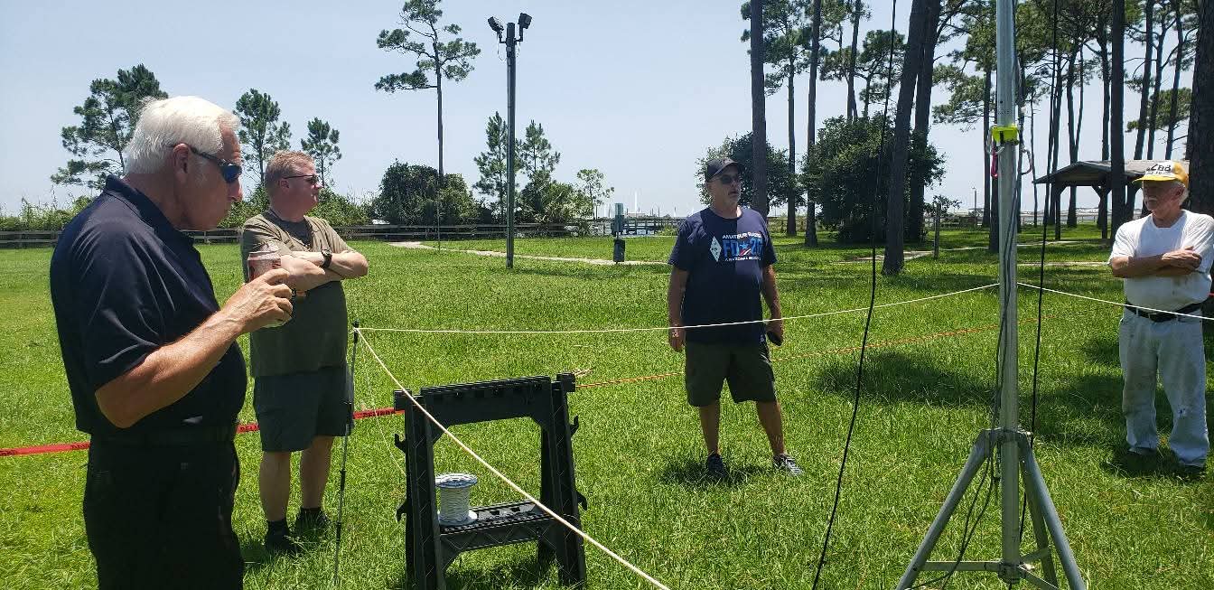
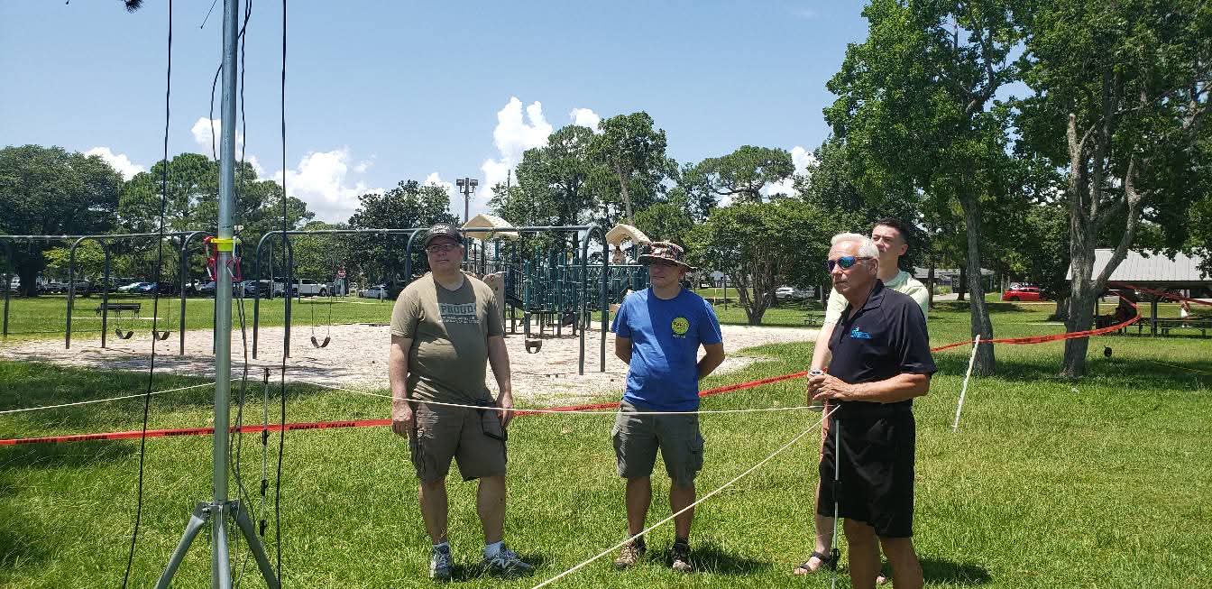
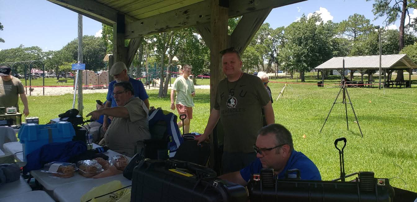
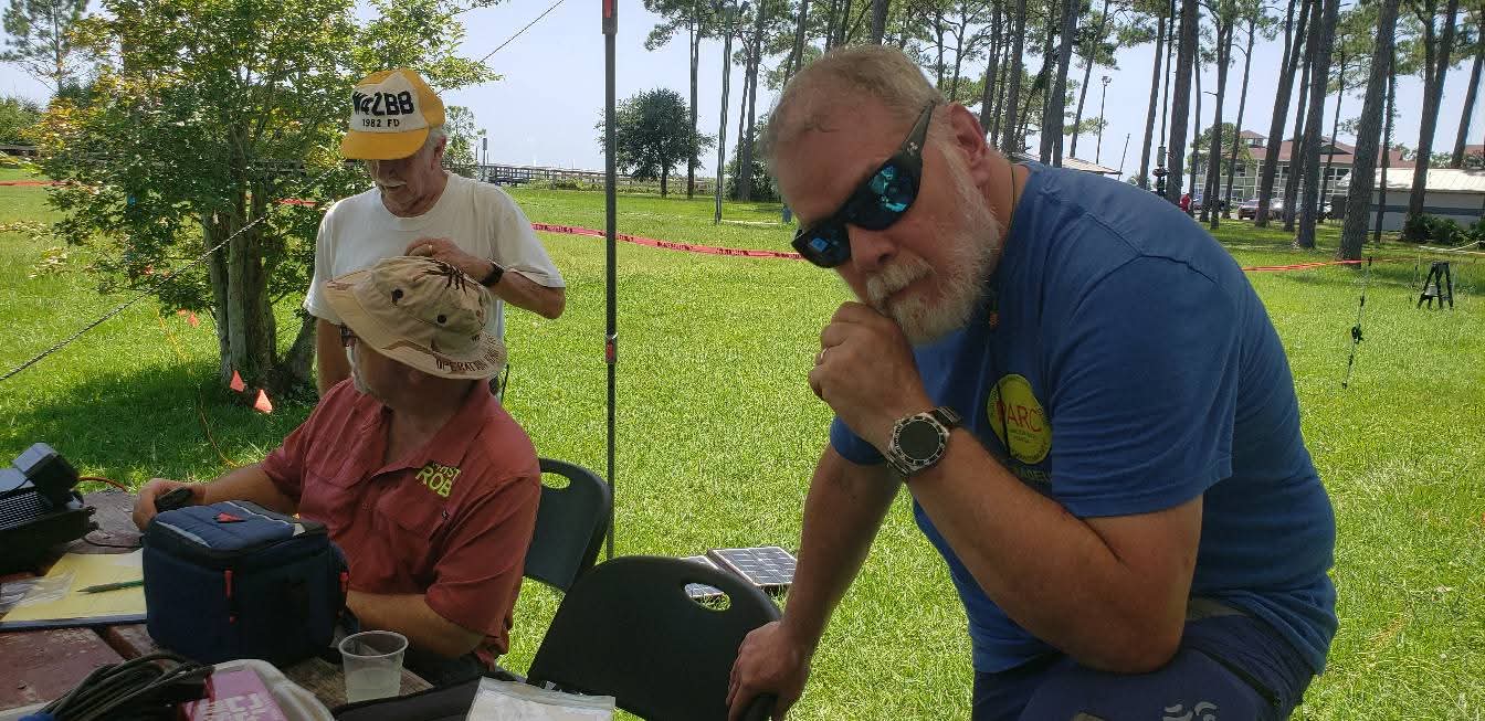
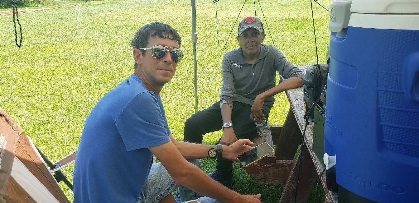
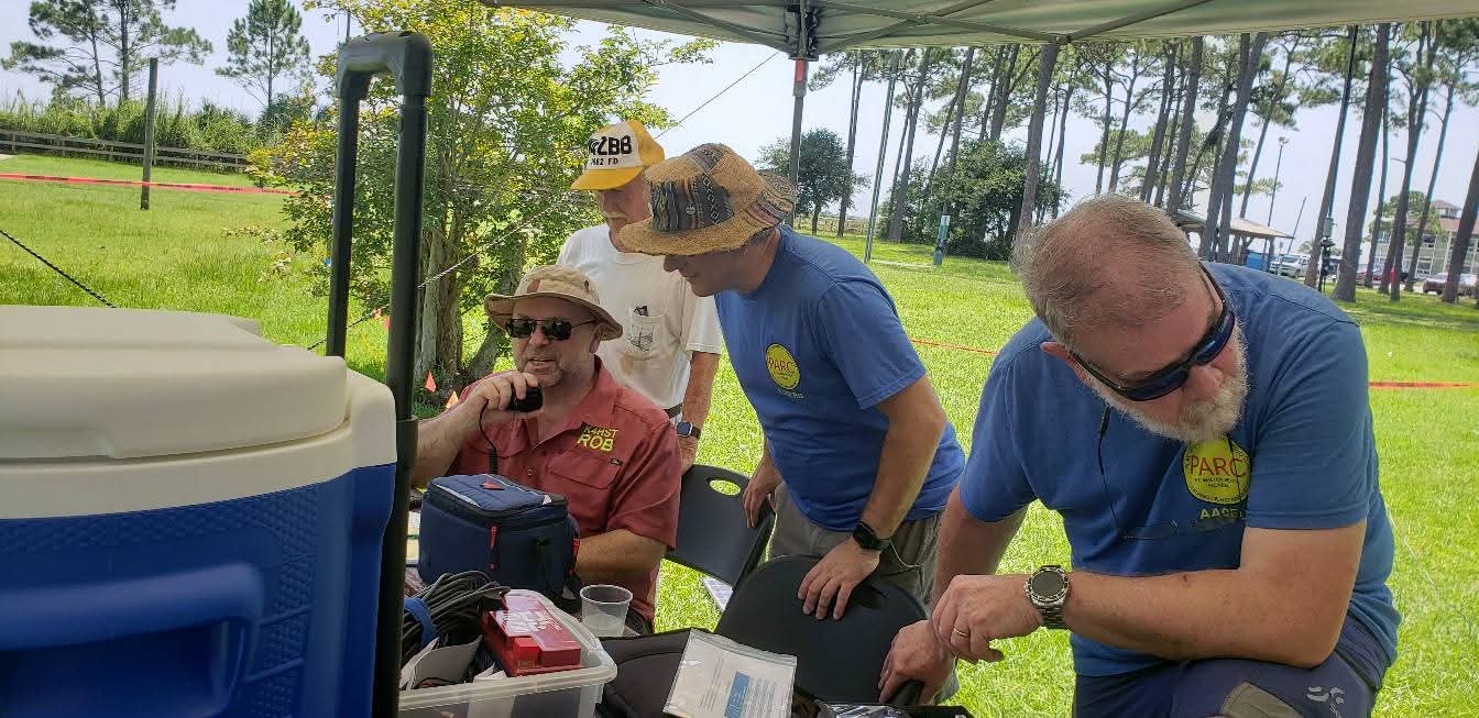
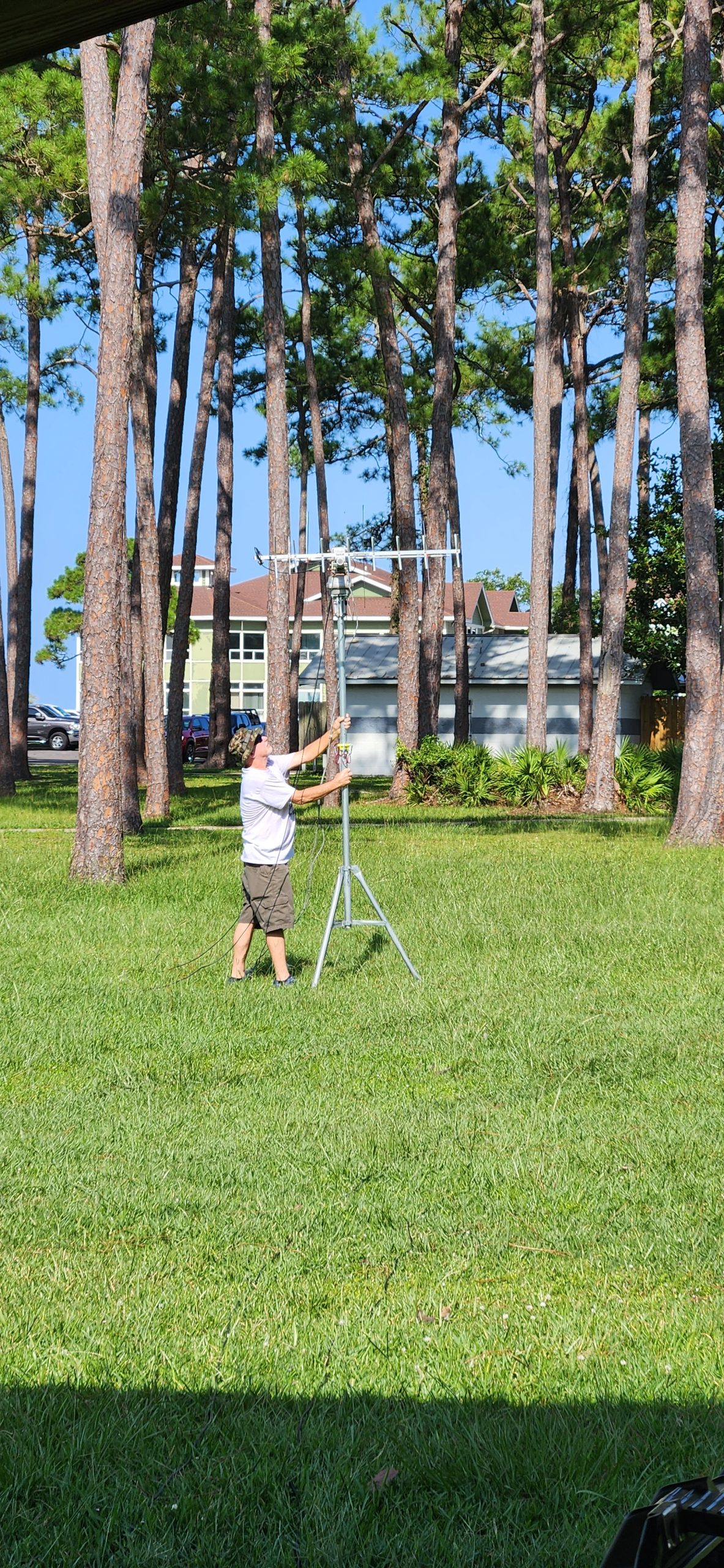
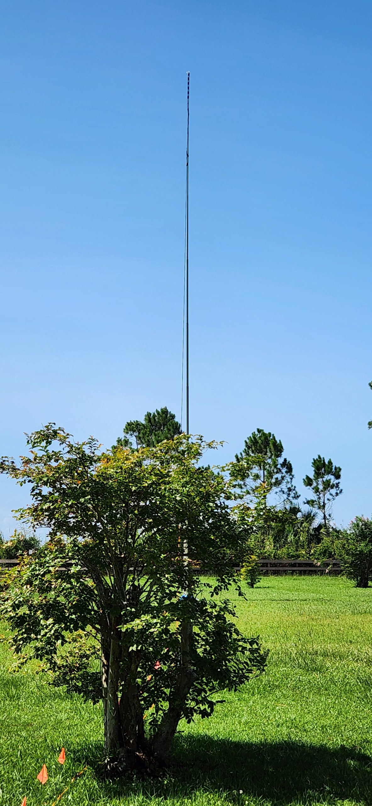
This was followed by a site sur4vey for the Field Day event at the end of this month! Multiple Hams gathered to goc over last Thursday’s presentation and see the property at Liz Jackson in person to map out the extensive and exciting antenna field!
Be sure to tune tune your RF to the Playground Amateur Radio Club!
What the what?! That’s right…
Not one, but two chances this coming weekend to enjoy some awesome RF challenges!
First up, From the original post:
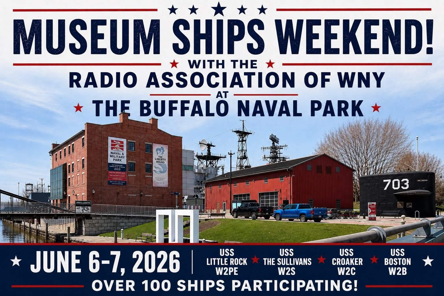
RAWNY will be joining over 100 other museum ships, June 6-7, for the annual Museum Ships Weekend – Amateur Radio Event! We will be on the air making contacts over ham radio from each of these vessels at the Buffalo and Erie County Naval and Military Park:
USS Little Rock – W2PE
USS The Sullivans – W2S
USS Croaker – W2C
USS Boston – W2B
The USS Boston SSN-703 is new for us this year. We will be operating from her memorial/sail, in front of the main museum building.
Look for each of these call signs spotted on POTA.app at US-6532 Erie Canalway, and the DX Cluster.
Second, New Month, New Challenges! Explore the US via the Lewis and Clark Trail! Get on the air and contact the stations along the route Lewis and Clark took to explore, map and record the Louisiana Purchase.
How many stations can you bag?
![]()
Good Luck and ham on!
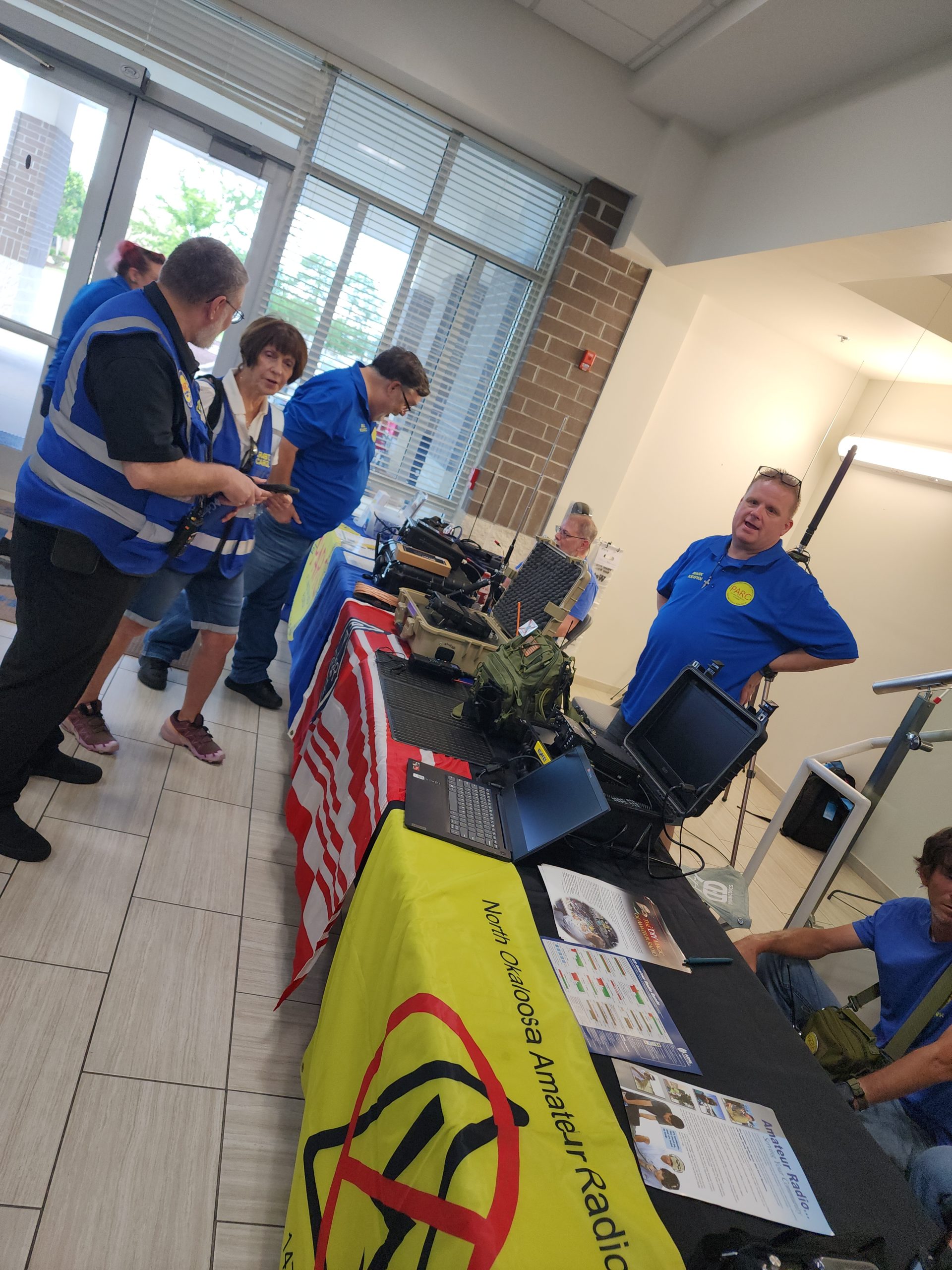
Okaloosa County’s Annual Hurricane Preparedness Expo is a free public event focused on hurricane readiness, disaster kits, and preparedness resources. For 2026, it was scheduled for Saturday, May 30, from 10 a.m. to 1 p.m. at the Okaloosa County Administration Building, 1250 N. Eglin Parkway in Shalimar.
The county described it as an opportunity to pick up free items for disaster kits, and local posts also mentioned food trucks and giveaways. Multiple county commissioners may attend, but the notice says it is not an official board meeting.
Learn about storm preparation before hurricane season ramps up.
Gather supplies or information for emergency kits.
Connect with county and community resources
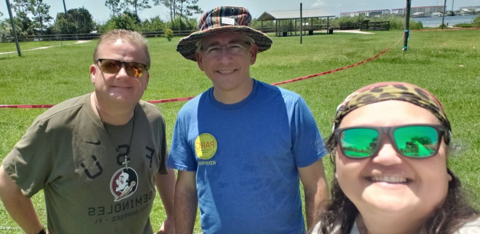
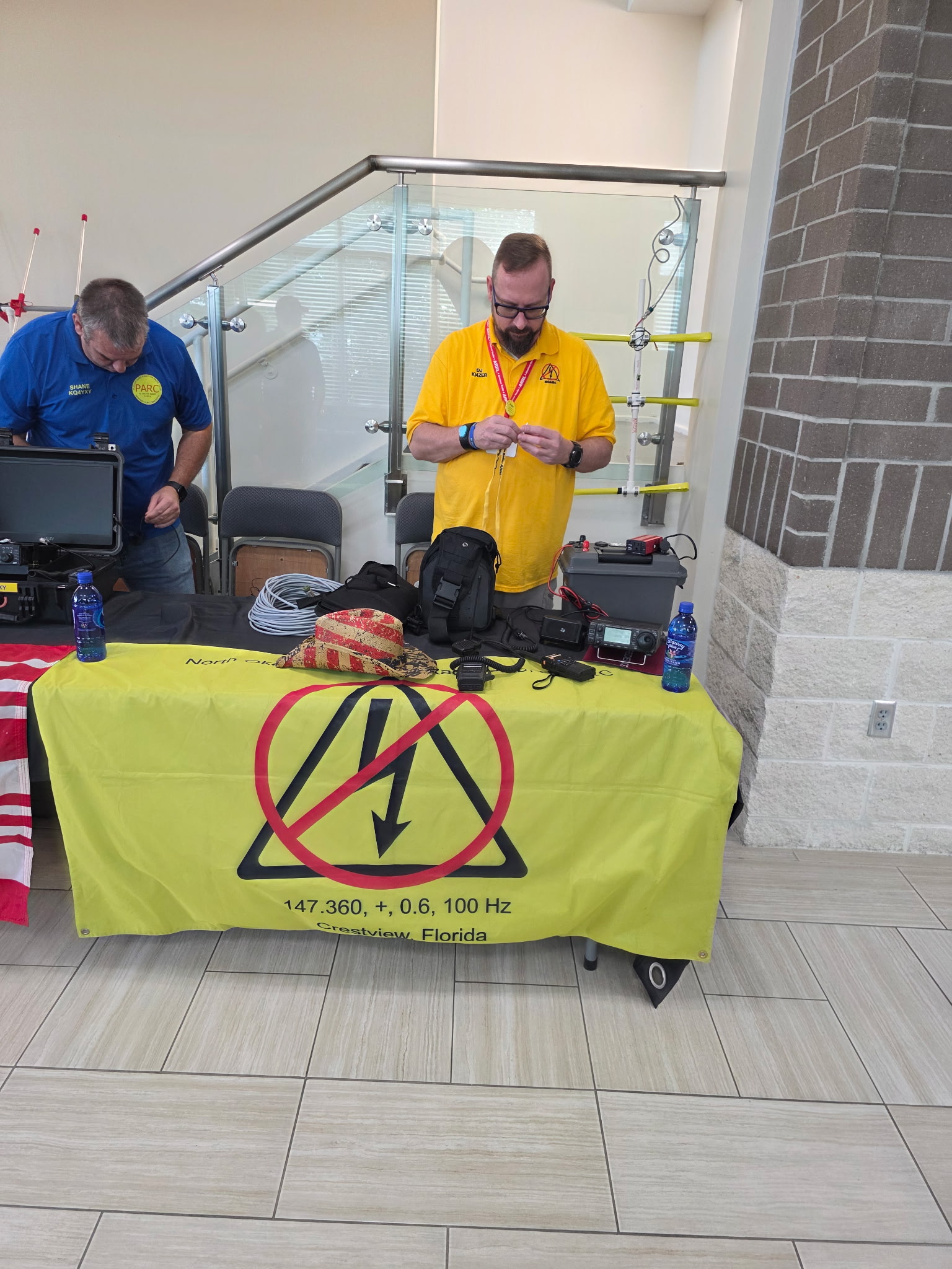
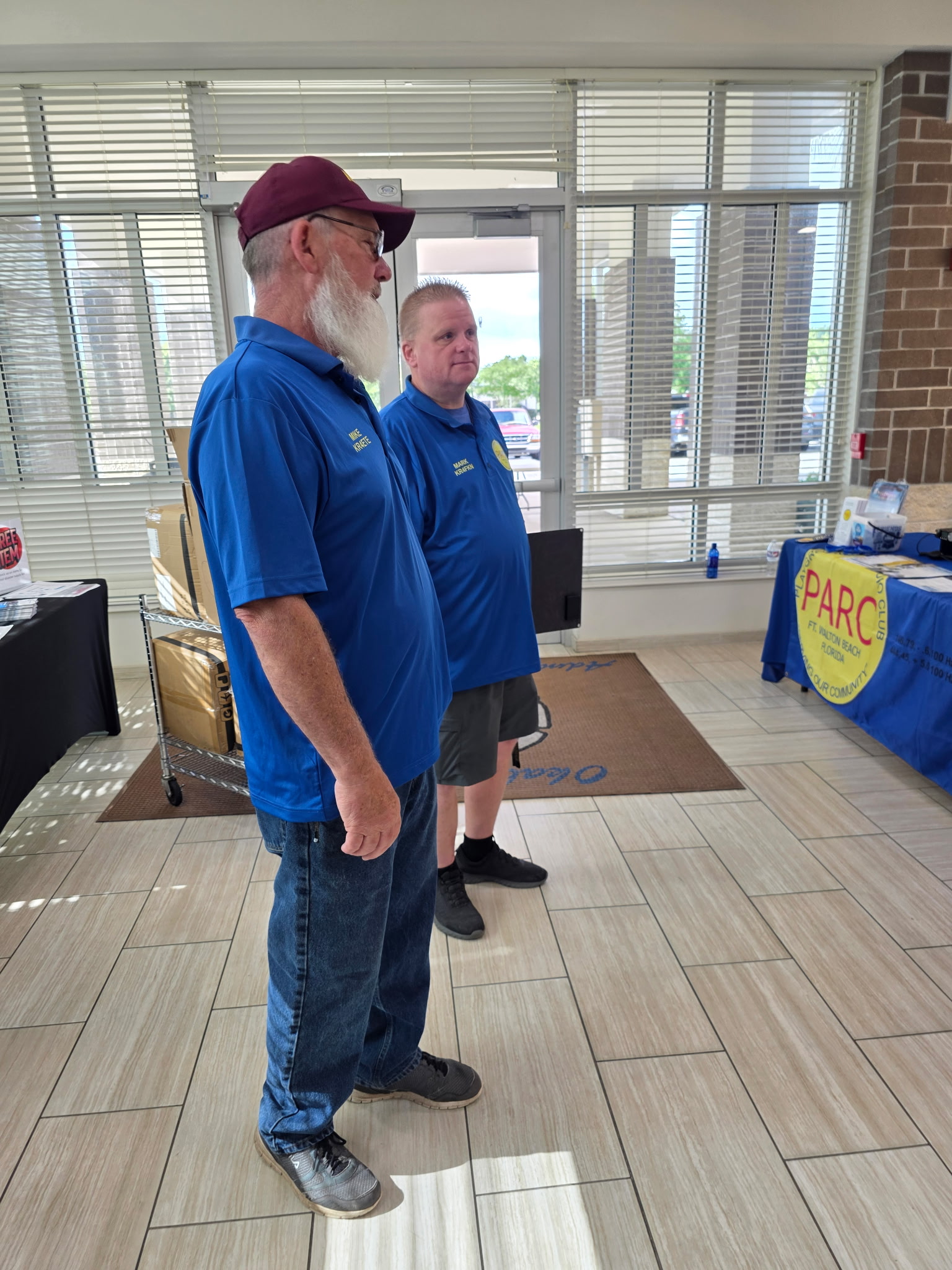
PARC Teamed up with the North Okaloosa Amateur Radio Club, Eglin Amateur Radio Society, the ARRL and others to promote Ham Radio! They all hosted live demonstrations of Radio and its usefulness!
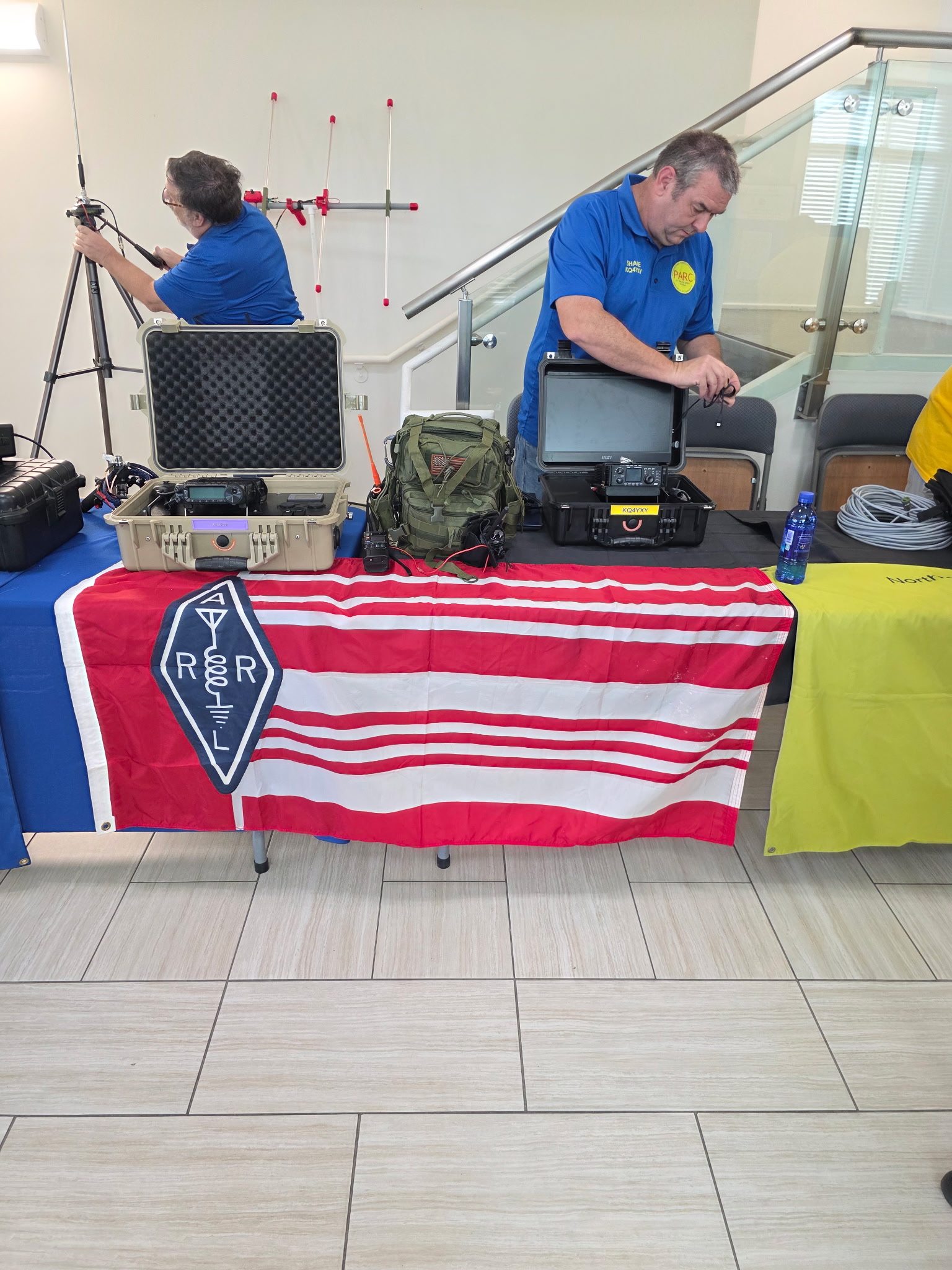
From the desk of KR4YXX!
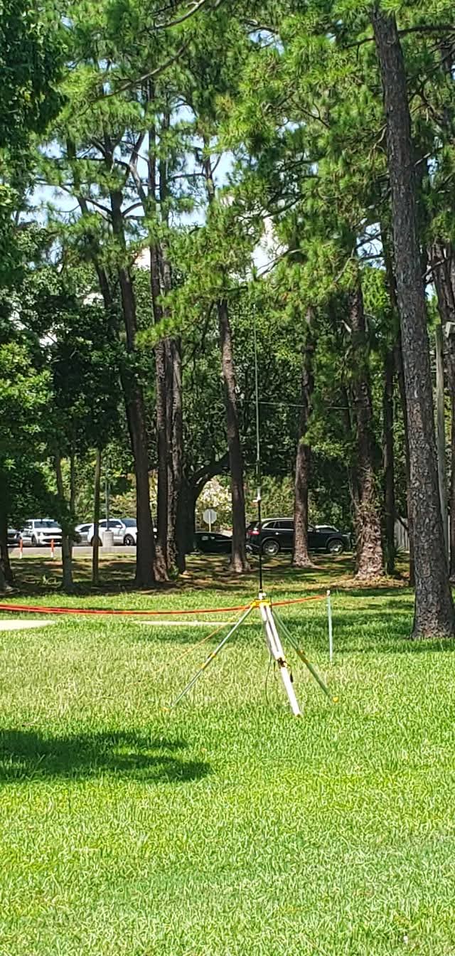
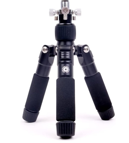
For POTA operations, the Yaesu ATAS-120A is best mounted on a tripod using a BuddiPole Vertical Antenna Clamp or a Gabil antenna tripod, which often includes thumbscrews for attaching ground radials. Operators frequently use the large TIA tripod or modified mini-tripods, ensuring the legs are extended and angled to provide stability against wind. A critical requirement for tripod use is adding a ground plane system; this typically involves installing 4 to 8 radials (often 1/4 wavelength for lower bands like 40m and 20m) to achieve acceptable SWR, as the antenna performs poorly without them.
For home use with HOA restrictions, the ATAS-120A can be mounted on a balcony rail using a Diamond CRM mount or a Vice Grip, or elevated on a 6-foot mast positioned at rain gutter height to remain unobtrusive. To maintain low SWR in these elevated setups, users have successfully run counterpoise wires inside rain gutters or along the structure, though this requires testing for electrical continuity. Alternatively, mounting the antenna on a ground spike with a robust radial system is an option, though it may be less aesthetically pleasing for some HOA environments compared to elevated, hidden counterpoises.
Powered by WordPress & Theme by Anders Norén